Safety
| WARNING – Never charge batteries that are damaged, deformed, swollen, have been exposed to fire, water, or a strong impact, or that exhibit abnormal heat or odor. |
Read the entire manual before use.
It is important that the OD Bike Charging Cabinet be installed and used in accordance with this manual and applicable regulations. Improper handling may result in personal injury or property damage.
General safety instructions
Only use the product for its intended purpose
OD Bike is a charging cabinet for electric bike batteries and may only be used for this purpose. Incorrect use can result in serious personal injury.
Installation must be performed by a qualified electrician
The product may only be installed by a qualified electrician in accordance with this installation manual. The electrician is responsible for ensuring that the installation complies with applicable laws, standards, and national installation requirements. The customer is responsible for ensuring that electrical wiring is installed correctly and in accordance with applicable regulations.
Properly sized wiring is required
All wiring must be sized in accordance with national installation requirements and restrictions.
Inspect the product before use
Before putting the product into service, inspect it for visible damage. The product must not be used if it is damaged or shows signs of malfunction.
Also check that ventilation openings are not blocked by leaves, snow, dirt, or other objects. Insufficient ventilation can lead to elevated temperatures and affect the charging cabinet’s operation.
Do not repair the product yourself
The product must not be opened, disassembled, or modified. Never insert foreign objects into any part of the cabinet.
Never submerge the product in water or subject it to rough handling.
Incorrect installation may cause damage
Incorrect installation or electrical connection may result in a risk of electric shock, fire or damage to persons and property.
| Do not leave compartments open longer than necessary when it rains. Make sure the battery and charger are dry before charging. If water has entered a compartment, do not begin charging until the compartment has been inspected and dried. |
Overview
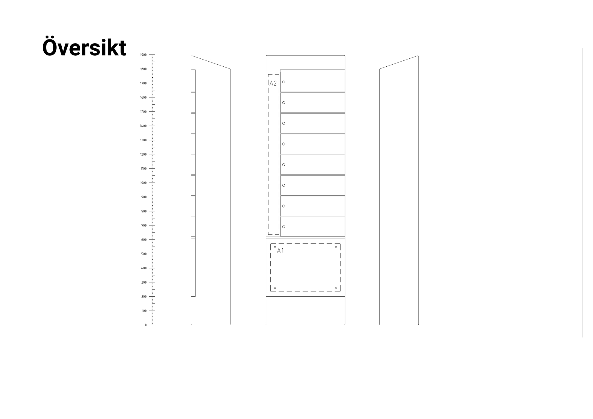
OD Bike consists of three main parts:
Locking function and access system
Mechanical padlock – simple and robust solution for manual locking.
Code lock – Locking via keypad
RFID lock – Contactless access via card or tag.
App (A) – Digital access via the GoRide app.
Cloud (C) – Administrator-controlled access and monitoring via the ACE Portal.
Entrance (E) – Integration with the customer's existing access control system.
Hardware
Charging cabinet with temperature control, ventilation, electrical outlets and locking system.
Electrical systems
Fuses, earth leakage switches and protective devices.
Technical Specification
| Product group | ECO Charge |
| Country of manufacture | Sweden |
| Measuring range (voltage) | 230 VAC, 1-phase, 50 Hz |
| Installation | Mounted on a solid base, concrete foundations are available as an option. Power supply should come up from below into the cabinet. |
| Dimensions (W x D x H) | 560 x 280 x 1900 mm |
| Dimensions of compartments (W x H) | 370 x 110 mm |
| Number of charging points | 8 (can be increased by combining several cabinets, example: 4 cabinets = 32 charging points) |
| Eluttag | 230 V schuko |
| Power source | 16 A, 3-phase |
| Maximum effect | 8A |
| Cable area | Min. 3 x 2.5 mm² |
| Materials | Galvanized sheet metal painted in RAL 9005 |
| Service hatch | Equipped with DIN lock and supplied key |
| Protection class | IP44 (protection against solid particles >1 mm and water splashes) Maximum installation altitude: 2,000 m above sea level. Relative humidity: 15–100% RH, non-condensing. |
| Weight | 71 kg (other models about 80-120 kg depending on configuration) |
| Displacement | Can be moved by pallet jack or forklift |
| Heating element | Thermostatic heating element, 250 W |
| Operational protection against moisture, condensation, and excessive temperature | - Thermostatically controlled heating (T1: start at 10 °C) - Overtemperature stop (T2: switch at 40 °C) - Automatic ventilation |
| Temperature range (operation) | Ambient temperature −15 °C to +35 °C, maximum altitude 2000 m, no explosive environments or corrosive chemicals. |
| ID labels | Used for identification of compartments in larger systems |
| Certifications | CE marked (meets European safety and quality requirements) |
| Sensors | Temperature sensors T1/T2 for controlling heating and charging |
| Options / Customizations | A= App control (GoRide), C= Cloud (integrated to 3rd party system) or E=Entrance (linked to wired access control system) |
Thermostat and temperature control
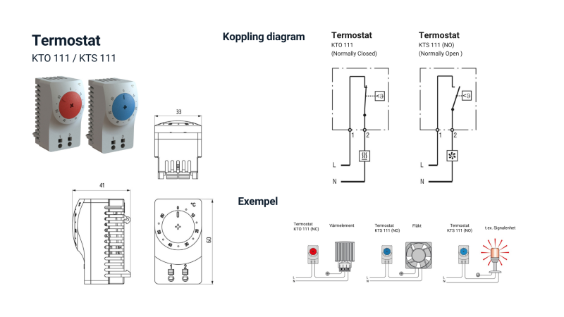
OD Bike is equipped with a dual sensor solution for temperature control:
Thermostat T1 (heating starts at 10 °C)
T1 sensor: starts the heater at approx. 10 °C to prevent moisture and condensation in the electronic components and ensure stable operation.
Thermostat T2 (overtemperature stop at 40 °C)
T2 sensor: stops charging at about 40 °C to prevent overheating.
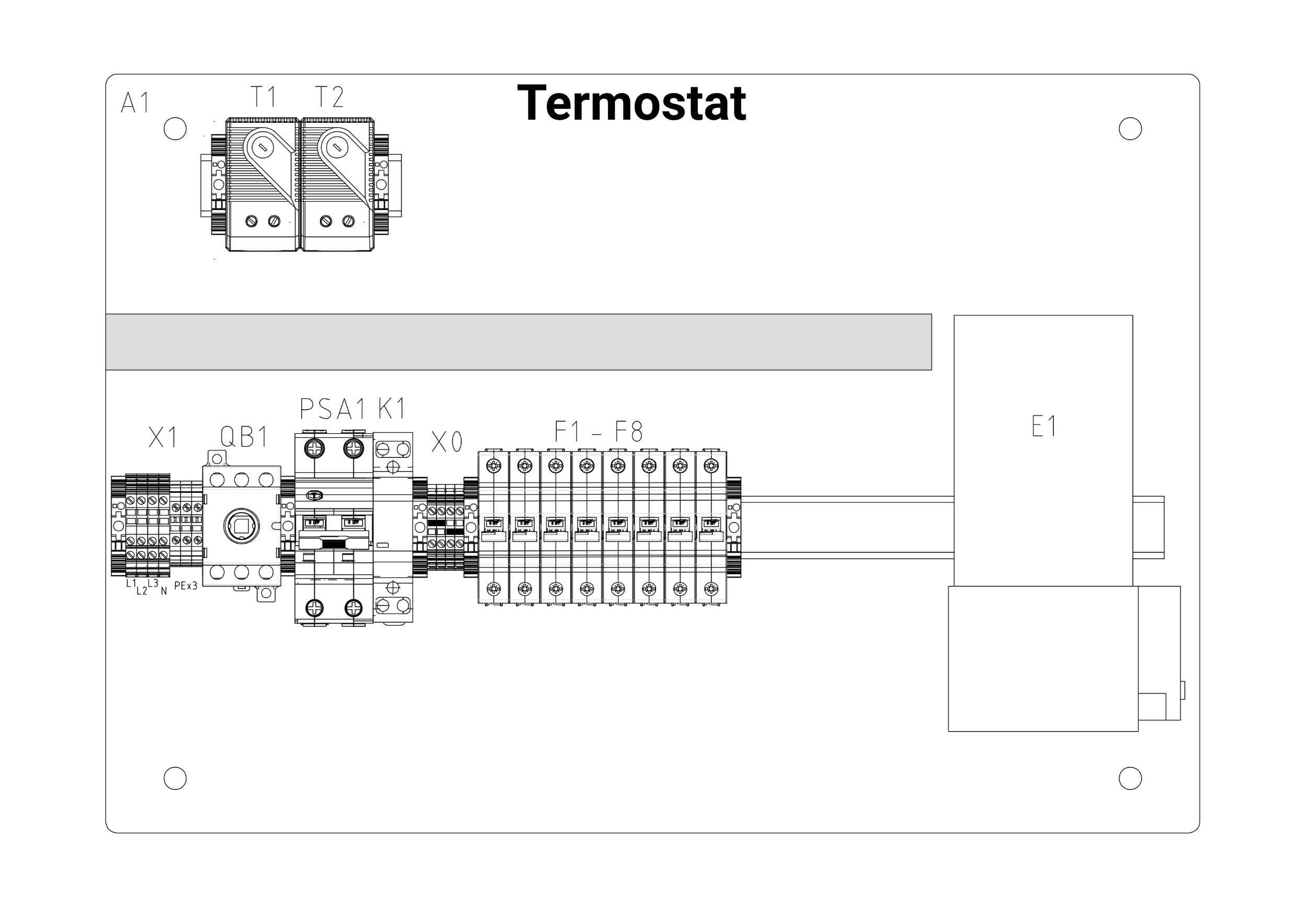
Temperature control and heating systems
The charging cabinet is equipped with a thermostat-controlled heating element that is activated at low temperatures.
The purpose is to reduce moisture and condensation in the cabinet and thus protect electronics and components from moisture-related malfunctions.
The heating system has a built-in overheating protection that cuts off the heat at abnormally high temperatures to protect the components.
The heating function is only intended for the cabinet's electronics and does not affect charging or battery temperature.
Placement groundwork and preparation
Soil conditions and substrates
The cabinet should always be placed on a flat and stable surface.
If necessary, ground work should be carried out to create an even mounting surface, as an uneven surface can lead to a skewed mounting or affect the function of the door. Depending on the surface, the following applies:
Cast concrete slab: Foundation is not needed.
Stone laying: The foundation should be buried or the concrete slab should be cast so that the plinth is level with the paving.
Loose soil / earth / gravel / asphalt: Use foundation or cast a concrete slab.
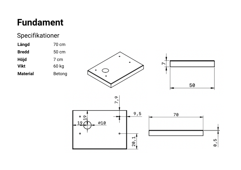
ECO Charge foundation
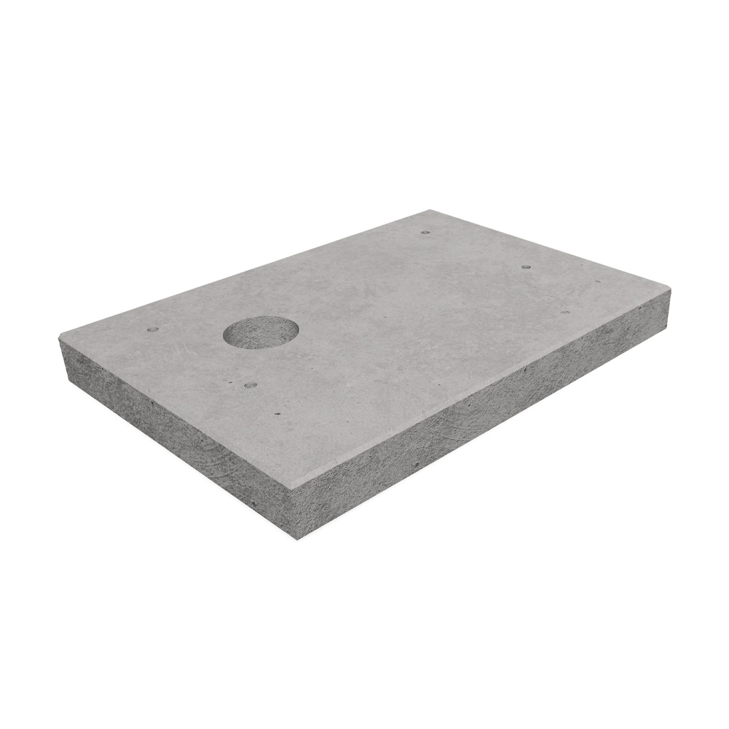
ECO Charge foundation is developed for secure attachment of ECO Charge charging cabinets.
The foundation, which is secured with ground anchors, has pre-drilled holes for easy mounting and is optimized for strength, stability and ease of installation.
Specifications
Weight 60 kg
Length 70 cm
Width 50 cm
Height 7 cm
Material Concrete
If a different foundation is used or a slab is poured, the installer must ensure that the power supply comes up in the right place and matches the cabinet.
Installation height
The recommended installation height is ground level, flush with the ground surface. When paving, the concrete base should always be buried so that the top is level with the surrounding surface.
Electricity supply
Ensure that power is supplied to the installation site before starting the installation.
Access to electrical connection must be provided as follows:
- 1 cabinet (8 charging points): approx. 1 A per charging point, total 8 A including fan and heating.
- Supply: 1 cabinet → 1-phase 230 V. Two or more cabinets → 3-phase 230 V.
The cabinets are equipped with a built-in residual current device and therefore do not need to be supplemented with an external one.
The power supply circuit must be sized in accordance with applicable national electrical installation codes. Verify that the power supply protection complies with the product’s rating data before commissioning.
Access and space
Consider access for both users and service. Leave enough space around the cabinet for ventilation (at least 3 cm per side) and for the door to open fully.
Recommended tools
| Smartphone, tablet or computer connected to a wireless network | |
| Allen key 6 mm | For mounting M8 screws |
| Socket wrench set | For the installation of bolts in concrete foundations. |
| Water passport | To ensure that the cabinet is mounted straight. |
| Multimeter | To measure voltage, current and resistance. Important when checking electrical connections. |
| Barrel sequencers | To ensure correct phase sequence for three-phase connection. |
| Voltage tester | To verify that cables are de-energized before starting work. |
| Insulation tester (megger) | To test the insulation resistance of the electrical system. |
| Earth leakage tester | To check that earth leakage circuit breakers are working properly. |
| Temperature meter (IR thermometer) | To check that the heating element and thermostats are working. |
| Pallyft | To move the cabinet over short distances. |
Package contents
Complete cabinet
Your key to the service hatch
Stickers: If the cabinet is in version A with the GoRide app function and is public, two stickers must be used – one for creating an account and one for booking.
Concrete foundation if this option has been selected, + 4 bolts.
Electrical connection
We recommend a 16 A, 3-phase power supply. This makes it easier if you want to add more cabinets later and ensures that the system is correctly dimensioned.
1 to 2 charging cabinets
Fuse: 3-phase 16A.
Power cable and cable between cabinets 1 and 2:
Max. FK 5G4mm² / EK 5G6mm²
If 3 to 6 charging cabinets
Fuse - 3-phase 16A.
Feeding cable, and cable between cabinets 1 - 6:
Max. FK 5G4mm², EK 5G6mm².
Load distribution:
When connecting 3 - 6 cabinets, cable 01 on the main switch must be moved as follows.
- In cabinets 2 and 5, cable 01 is moved from L1 to L2 on the main switch.
- In cabinets 3 and 6, cable 01 is moved from L1 to L3 on the main switch
Wiring diagram
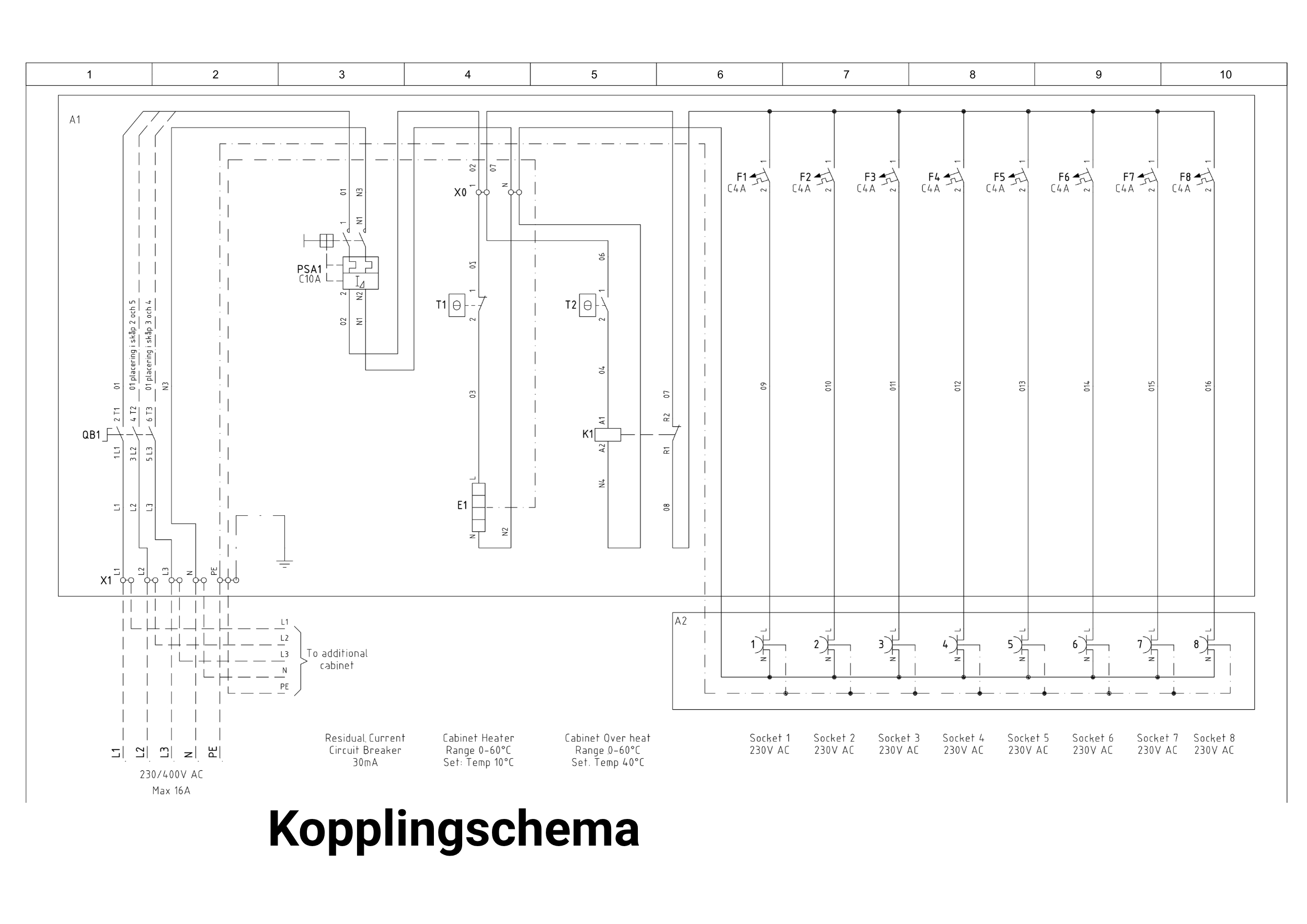
The maximum power for OD BIKE 8 is 8 A.
Power supply must be 3-phase 230 V.
Installation steps - electrical connection
Installation of a charging cabinet with a base
Remove the base from the charging cabinet
- Open the service hatch
- Check the base of the charging cabinet to identify the mounting brackets that hold the base in place.
- Use appropriate tools to loosen and remove the mounting brackets from the base.
- Carefully lift the base off the charging cabinet. Make sure the mounting area is clear and easily accessible.
Prepare the installation site
- Choose a suitable location for the plinth. The location should be level, stable and meet the requirements for electrical installation.
- If necessary - prepare the substrate with a cast concrete base or other solid anchorage to ensure stability.
Installing the plinth
- Place the plinth in the prepared place.
- Use a spirit level to check that the plinth is level.
- Fix the plinth with bolts or screws as recommended for the substrate.
- Make sure that the plinth is firmly attached and cannot move.
Place the charging cabinet on the plinth
- Lift the charging cabinet into place on top of the mounted plinth.
- Check that the enclosure is centered and aligned with the base fasteners.
- Screw the charging cabinet to the base with the supplied fasteners.
Electrical connection
- Ensure that the power supply is switched off.
- Insert cables through the cable entry, mark them, and pull them into the cabinet.
about the "Entrance" lock function, insert the power supply to the access control system. - Connect the cables according to the wiring diagram. For single-phase installations, use L1, N, and PE. Make sure the cables do not come into contact with sharp metal edges or moving parts. All cables must be mechanically protected and properly secured.
Commissioning
Pre-checklist:
- safety officer
- cable glands
- cable installation
- gaps
- service hatch
- ventilation
- ground fault circuit interrupter
- withdrawals verified
- Turn on the power supply.
- Check that the enclosure is working by observing indicator lights or other operating information.
- Test any locking and security features as per separate instructions.
- Close the service door and lock it.
- Check that there is no abnormal heating, odor, or unusual noise during the first few minutes after startup.
Locking functions and access systems
OD Bike can be equipped with several types of locking functions. Functions such as ACE App (A), ACE Cloud (C), and ACE Entrance (E) are developed and documented by EWF Eco. For other types of locks, such as RFID and code locks, please refer to the respective supplier's manuals for installation and operation.
Activation App (A) via GoRide
As an administrator (ordering party), you are responsible for creating your organization's account and inviting users. A detailed administrator guide can be found on the landing page provided by the provider here:
Short workflow:
- Create an administrator account in GoRide and register your organization.
- Link the locker to your organization's account.
- Assign access to selected bays/charging points.
- Manage permissions and track usage in the portal.
Activation Cloud (C) via ACE Portal
ACE Portal - login
Go to the ACE Portal:
https://ewfecoaceportal-eybvcqbxekgcf2e5.swedencentral-01.azurewebsites.net
Log in with your account. The account is created in advance by an ACE administrator.
If you have not received a user account, please contact support@ewfeco.com
Authorizations
To activate the ACE Portal, different authorization levels are used. The relevant steps depend on whether you are a reseller (ÅF), customer or installer/service. All the steps below are described in detail, but please note that not all steps are necessary for all users.
- Reseller: Can create new customers and manage the customers you have created.
- Customer: Can only manage its own organization and users.
- Installation/Service: Can manage the resources (cabinets) assigned by the dealer or customer.
Guidance for activation
- If you are a new retailer, start with Create new customer.
- If you are already a customer or ÅF with existing cabinets, go directly to Create new user.
- Create new city is only used in cases where geographical structuring is needed (e.g. municipalities with several cabinets in different locations).
To create a new customer:
- Press "CREATE NEW CUSTOMER"
- Select the type of customer to be created:
Reseller - Has rights to create other customers and manage the customers created by the reseller.
Customer - Has rights to manage only himself
Installation / Service - Has rights to manage only the resources that have been assigned to them by Customers or Resellers. - Enter a name for the new customer.
- Press "ADD CUSTOMER"
To create a new user:
- Select a customer.
- Press on "MANAGE USERS".
- Press "CREATE NEW USER"
- Enter the user's e-mail address.
- Enter a password.
- Select the level the user should be
- Click on "Register".
- Communicate passwords to the user.
To create a new city:
- Select which customer the city should be created under.
- Press "CREATE NEW CITY"
- Enter the name of the city.
- Press "ADD CITY".
To create a new area:
- Select customer
- Select the city under which the area will be created.
- Press "CREATE NEW AREA"
- Enter the name of the area.
- Press "ADD AREA"
To create a new installation:
- Select customer
- Select city
- Select the area under which the installation will be created.
- Press "CREATE NEW INSTALLATION"
- Enter the name of the installation.
- Press "ADD INSTALLATION
Linking physical cabinet to installation in ACE.Portal
An installer scans a QR code located inside the enclosure service door. The QR code takes the installer to a page on the portal where the installer selects:
Customer
City
Area
Installation
Presses "OK".
This then links this set of cabinets to the installation.
Activation Entrance (E) via access control system
Integration is done in consultation with the client's access control system supplier.
About the product
Environment and recycling
ECO Charge ACE contains electrical and electronic components and must not be disposed of with household waste. To minimize the environmental impact, the product should be recycled or disposed of safely in accordance with local rules and regulations.
- Take the product to a recycling center or other place for electronics recycling.
- Contact your municipality for information on proper handling.
- By recycling, you contribute to a more circular and sustainable use of resources.
Certifications and labels
ECO Charge ACE complies with relevant standards and directives for electrical safety and quality.
The product is CE marked and certified for the EU market according to applicable directives.
- 2011/65/EU - RoHS Directive
- EN 60950-1:2001 + A11:2004
- 2014/35/EC - Low Voltage Directive (LVD)
The product is designed and manufactured in accordance with these standards to ensure the highest quality and safety.
Warranty and liability
The warranty period is 1 year (with the possibility of an extended warranty of up to 5 years).
Failure to comply with the instructions, directions and safety measures in this manual will void the warranty.
EWF Eco disclaims all claims for compensation for damages or incidents arising directly or indirectly from non-compliance with this manual.
- The installation must be carried out by a qualified electrician in accordance with applicable laws and regulations.
- EWF Eco is not responsible for the consequences of improper installation or use.
- EWF Eco reserves the right to update the content of this document at any time without prior notice.
Limitation of liability
The manufacturer does not warrant the accuracy or completeness of the information contained in this document and accepts no liability for any consequences arising from the use of the information.
This includes indirect damage, downtime or financial losses that may arise from the use of the product or the manual.
Operation, maintenance & cleaning
Ventilation
Ventilation openings must be kept free of dirt, leaves, snow, and other obstructions.
- The charging cabinets are designed for trouble-free use and normally require no maintenance.
- Clean the charging cabinets with a mild detergent and a damp cloth. Never use a pressure washer, steam cleaner, solvents, or corrosive cleaning agents.
- Monthly check: Visual check of cabinets, wiring and ventilation.
- Quarterly: Functional test of locks, lighting and sockets.
- Annually: Inspection by a qualified technician. Check the ground connection, cable entries, seals, corrosion, screw connections, and ground fault circuit interrupters.
- Always use original EWF Eco spare parts.
Support
For warranty, support and service issues, please contact your dealer in the first instance.
Product and operational questions:
support@ewfeco.se | 010-4952495